NASA Solar Eclipse Bulletins
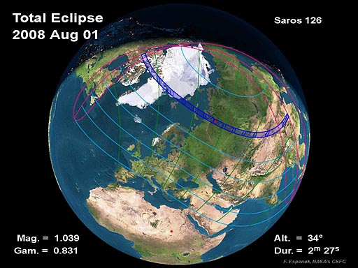
NASA/TP-2007-214149: Total Solar Eclipse of 2008 August 01
3. Observing the Eclipse
3.1 Eye Safety and Solar Eclipses
A total solar eclipse is probably the most spectacular astronomical event that many people will experience in their lives. There is a great deal of interest in watching eclipses, and thousands of astronomers (both amateur and professional) and other eclipse enthusiasts travel around the world to observe and photograph them.
A solar eclipse offers students a unique opportunity to see a natural phenomenon that illustrates the basic principles of mathematics and science taught through elementary and secondary school. Indeed, many scientists (including astronomers) have been inspired to study science as a result of seeing a total solar eclipse. Teachers can use eclipses to show how the laws of motion and the mathematics of orbits can predict the occurrence of eclipses. The use of pinhole cameras and telescopes or binoculars to observe an eclipse leads to an understanding of the optics of these devices. The rise and fall of environmental light levels during an eclipse illustrate the principles of radiometry and photometry, while biology classes can observe the associated behavior of plants and animals. It is also an opportunity for children of school age to contribute actively to scientific research—observations of contact timings at different locations along the eclipse path are useful in refining our knowledge of the orbital motions of the Moon and Earth, and sketches and photographs of the solar corona can be used to build a three-dimensional picture of the Sun’s extended atmosphere during the eclipse.
Observing the Sun, however, can be dangerous if the proper precautions are not taken. The solar radiation that reaches the surface of the Earth ranges from ultraviolet (UV) radiation at wavelengths longer than 290 nm, to radio waves in the meter range. The tissues in the eye transmit a substantial part of the radiation between 380–400 nm to the light-sensitive retina at the back of the eye. While environmental exposure to UV radiation is known to contribute to the accelerated aging of the outer layers of the eye and the development of cataracts, the primary concern over improper viewing of the Sun during an eclipse is the development of “eclipse blindness” or retinal burns.
Exposure of the retina to intense visible light causes damage to its light-sensitive rod and cone cells. The light triggers a series of complex chemical reactions within the cells which damages their ability to respond to a visual stimulus, and in extreme cases, can destroy them. The result is a loss of visual function, which may be either temporary or permanent depending on the severity of the damage. When a person looks repeatedly, or for a long time, at the Sun without proper eye protection, this photochemical retinal damage may be accompanied by a thermal injury—the high level of visible and near-infrared radiation causes heating that literally cooks the exposed tissue. This thermal injury or photocoagulation destroys the rods and cones, creating a small blind area. The danger to vision is significant because photic retinal injuries occur without any feeling of pain (the retina has no pain receptors), and the visual effects do not become apparent for at least several hours after the damage is done (Pitts 1993). Viewing the Sun through binoculars, a telescope, or other optical devices without proper protective filters can result in immediate thermal retinal injury because of the high irradiance level in the magnified image.
The only time that the Sun can be viewed safely with the naked eye is during a total eclipse, when the Moon completely covers the disk of the Sun. It is never safe to look at a partial or annular eclipse, or the partial phases of a total solar eclipse, without the proper equipment and techniques. Even when 99% of the Sun’s surface (the photosphere) is obscured during the partial phases of a solar eclipse, the remaining crescent Sun is still intense enough to cause a retinal burn, even though illumination levels are comparable to twilight (Chou 1981 and 1996, and Marsh 1982). Failure to use proper observing methods may result in permanent eye damage and severe visual loss. This can have important adverse effects on career choices and earning potential, because it has been shown that most individuals who sustain eclipse-related eye injuries are children and young adults (Penner and McNair 1966, Chou and Krailo 1981, and Michaelides et al. 2001).
The same techniques for observing the Sun outside of eclipses are used to view and photograph annular solar eclipses and the partly eclipsed Sun (Sherrod 1981, Pasachoff 2000, Pasachoff and Covington 1993, and Reynolds and Sweetsir 1995). The safest and most inexpensive method is by projection. A pinhole or small opening is used to form an image of the Sun on a screen placed about a meter behind the opening. Multiple openings in perfboard, a loosely woven straw hat, or even interlaced fingers can be used to cast a pattern of solar images on a screen. A similar effect is seen on the ground below a broad-leafed tree: the many “pinholes” formed by overlapping leaves creates hundreds of crescent-shaped images. Binoculars or a small telescope mounted on a tripod can also be used to project a magnified image of the Sun onto a white card. All of these methods can be used to provide a safe view of the partial phases of an eclipse to a group of observers, but care must be taken to ensure that no one looks through the device. The main advantage of the projection methods is that nobody is looking directly at the Sun. The disadvantage of the pinhole method is that the screen must be placed at least a meter behind the opening to get a solar image that is large enough to be easily seen.
The Sun can only be viewed directly when filters specially designed to protect the eyes are used. Most of these filters have a thin layer of chromium alloy or aluminum deposited on their surfaces that attenuates both visible and near-infrared radiation. A safe solar filter should transmit less than 0.003% (density ~4.5) of visible light and no more than 0.5% (density ~2.3) of the near-infrared radiation from 780–1400 nm. (In addition to the term transmittance [in percent], the energy transmission of a filter can also be described by the term density [unitless] where density, d, is the common logarithm of the reciprocal of transmittance, t, or d=log10[1/t]. A density of ‘0’ corresponds to a transmittance of 100%; a density of ‘1’ corresponds to a transmittance of 10%; a density of ‘2’ corresponds to a transmittance of 1%, etc.). Figure 18 shows transmittance curves for a selection of safe solar filters.
One of the most widely available filters for safe solar viewing is shade number 14 welder’s glass, which can be obtained from welding supply outlets. A popular inexpensive alternative is aluminized polyester that has been specially made for solar observation. (This material is commonly known as “mylar,” although the registered trademark “Mylar®” belongs to Dupont, which does not manufacture this material for use as a solar filter. Note that “Space blankets” and aluminized polyester film used in gardening are NOT suitable for this purpose!) Unlike the welding glass, aluminized polyester can be cut to fit any viewing device, and does not break when dropped. It has been pointed out that some aluminized polyester filters may have large (up to approximately 1 mm in size) defects in their aluminum coatings that may be hazardous. A microscopic analysis of examples of such defects shows that despite their appearance, the defects arise from a hole in one of the two aluminized polyester films used in the filter. There is no large opening completely devoid of the protective aluminum coating. While this is a quality control problem, the presence of a defect in the aluminum coating does not necessarily imply that the filter is hazardous. When in doubt, an aluminized polyester solar filter that has coating defects larger than 0.2 mm in size, or more than a single defect in any 5 mm circular zone of the filter, should not be used.
An alternative to aluminized polyester that has become quite popular is “black polymer” in which carbon particles are suspended in a resin matrix. This material is somewhat stiffer than polyester film and requires a special holding cell if it is to be used at the front of binoculars, telephoto lenses, or telescopes. Intended mainly as a visual filter, the polymer gives a yellow image of the Sun (aluminized polyester produces a blue-white image). This type of filter may show significant variations in density of the tint across its extent; some areas may appear much lighter than others. Lighter areas of the filter transmit more infrared radiation than may be desirable. The advent of high resolution digital imaging in astronomy, especially for photographing the Sun, has increased the demand for solar filters of higher optical quality. Baader AstroSolar Safety Film, a metal-coated resin, can be used for both visual and photographic solar observations. A much thinner material, it has excellent optical quality and much less scattered light than polyester filters. The Baader material comes in two densities: one for visual use and a less dense version optimized for photography. Filters using optically flat glass substrates are available from several manufacturers, but are quite expensive in large sizes.
Many experienced solar observers use one or two layers of black-and-white film that has been fully exposed to light and developed to maximum density. The metallic silver contained in the film emulsion is the protective filter; however, any black-and-white negative with images in it is not suitable for this purpose. More recently, solar observers have used floppy disks and compact disks (CDs and CD-ROMs) as protective filters by covering the central openings and looking through the disk media. However, the optical quality of the solar image formed by a floppy disk or CD is relatively poor compared to aluminized polyester or welder’s glass. Some CDs are made with very thin aluminum coatings that are not safe—if the CD can be seen through in normal room lighting, it should not be used! No filter should be used with an optical device (e.g., binoculars, telescope, camera) unless it has been specifically designed for that purpose and is mounted at the front end. Some sources of solar filters are listed below.
Unsafe filters include color film, black-and-white film that contains no silver (i.e., chromogenic film), film negatives with images on them, smoked glass, sunglasses (single or multiple pairs), photographic neutral density filters and polarizing filters. Most of these transmit high levels of invisible infrared radiation, which can cause a thermal retinal burn (see Figure 23). The fact that the Sun appears dim, or that no discomfort is felt when looking at the Sun through the filter, is no guarantee that the eyes are safe.
Solar filters designed to thread into eyepieces that are often provided with inexpensive telescopes are also unsafe. These glass filters often crack unexpectedly from overheating when the telescope is pointed at the Sun, and retinal damage can occur faster than the observer can move the eye from the eyepiece. Avoid unnecessary risks. Local planetariums, science centers, or amateur astronomy clubs can provide additional information on how to observe the eclipse safely.
There are some concerns that ultraviolet-A (UVA) radiation (wavelengths from 315–380 nm) in sunlight may also adversely affect the retina (Del Priore 1999). While there is some experimental evidence for this, it only applies to the special case of aphakia, where the natural lens of the eye has been removed because of cataract or injury, and no UV-blocking spectacle, contact or intraocular lens has been fitted. In an intact normal human eye, UVA radiation does not reach the retina because it is absorbed by the crystalline lens. In aphakia, normal environmental exposure to solar UV radiation may indeed cause chronic retinal damage. The solar filter materials discussed in this article, however, attenuate solar UV radiation to a level well below the minimum permissible occupational exposure for UVA (ACGIH 2004), so an aphakic observer is at no additional risk of retinal damage when looking at the Sun through a proper solar filter.
In the days and weeks before a solar eclipse, there are often news stories and announcements in the media, warning about the dangers of looking at the eclipse. Unfortunately, despite the good intentions behind these messages, they frequently contain misinformation, and may be designed to scare people from viewing the eclipse at all. This tactic may backfire, however, particularly when the messages are intended for students. A student who heeds warnings from teachers and other authorities not to view the eclipse because of the danger to vision, and later learns that other students did see it safely, may feel cheated out of the experience. Having now learned that the authority figure was wrong on one occasion, how is this student going to react when other health-related advice about drugs, AIDS, or smoking is given (Pasachoff 2001). Misinformation may be just as bad, if not worse, than no information.
Remember that the total phase of an eclipse can, and should, be seen without any filters, and certainly never by projection! It is completely safe to do so. Even after observing 14 solar eclipses, the author finds the naked-eye view of the totally eclipsed Sun awe-inspiring. The experience should be enjoyed by all.
Sect. 3.1 was contributed by:
B. Ralph Chou, MSc, ODAssociate Professor, School of Optometry
University of Waterloo
Waterloo, Ontario, Canada N2L 3G1
3.2 Sources for Solar Filters
The following is a brief list of sources for filters that are specifically designed for safe solar viewing with or without a telescope. The list is not meant to be exhaustive, but is a representative sample of sources for solar filters currently available in North America and Europe. For additional sources, see advertisements in Astronomy and or Sky & Telescope magazines. (The inclusion of any source on the following list does not imply an endorsement of that source by either the authors or NASA.)
Sources in the USA:
- American Paper Optics, 3080 Bartlett Corporate Drive, Bartlett, TN 38133, (800) 767-8427 or (901) 381-1515
- Astro-Physics, Inc., 11250 Forest Hills Rd., Rockford, IL 61115, (815) 282-1513.
- Celestron International, 2835 Columbia Street, Torrance, CA 90503, (310) 328-9560.
- Coronado Technology Group, 1674 S. Research Loop, Suite 436, Tucson, AZ 85710-6739, (520) 760-1561, (866) SUNWATCH.
- Meade Instruments Corporation, 16542 Millikan Ave., Irvine, CA 92606, (714) 756-2291.
- Rainbow Symphony, Inc., 6860 Canby Ave., #120, Reseda, CA 91335, (818) 708-8400.
- Telescope and Binocular Center, P.O. Box 1815, Santa Cruz, CA 95061-1815, (408) 763-7030.
- Thousand Oaks Optical, Box 4813, Thousand Oaks, CA 91359, (805) 491-3642.
Sources in Canada:
- Kendrick Astro Instruments, 2920 Dundas St. W., Toronto, Ontario, Canada M6P 1Y8, (416) 762-7946.
- Khan Scope Centre, 3243 Dufferin Street, Toronto, Ontario, Canada M6A 2T2, (416) 783-4140.
- Perceptor Telescopes TransCanada, Brownsville Junction Plaza, Box 38, Schomberg, Ontario, Canada L0G 1T0, (905) 939-2313.
Sources in Europe:
- Baader Planetarium GmbH, Zur Sternwarte, 82291 Mammendorf, Germany, 0049 (8145) 8802.
3.3 Eclipse Photography
The eclipse may be safely photographed provided that the above precautions are followed. Almost any kind of camera can be used to capture this rare event, but Single Lens Reflex (SLR) cameras offer interchangable lenses and zooms. A lens with a fairly long focal length is recommended in order to produce as large an image of the Sun as possible. A standard 50 mm lens on a 35 mm film camera yields a minuscule 0.5 mm solar image, while a 200 mm telephoto or zoom lens produces a 1.9 mm image (Figure 19). A better choice would be one of the small, compact, catadioptic or mirror lenses that have become widely available in the past 20 years. The focal length of 500 mm is most common among such mirror lenses and yields a solar image of 4.6 mm.
With one solar radius of corona on either side, an eclipse view during totality will cover 9.2 mm. Adding a 2x teleconverter will produce a 1000 mm focal length, which doubles the Sun’s diameter to 9.2 mm. Focal lengths in excess of 1000 mm usually fall within the realm of amateur telescopes.
Consumer digital cameras have become affordable in recent years and many of these may be used to photograph the eclipse. Most recommendations for 35 mm SLR cameras apply to digital SLR (DSLR) cameras as well. The primary difference is that the imaging chip in most DSLR cameras is only about 2/3 the area of a 35 mm film frame (check the camera’s technical specifications). This means that the Sun’s relative size will be 1.5 times larger in a DSLR camera so a shorter focal length lens can be used to achieve the same angular coverage compared to a 35 mm SLR camera. For example, a 500 mm lens on a digital camera produces the same relative image size as a 750 mm lens on a 35 mm camera (Figure 19). Another issue to consider is the lag time between digital frames required to write images to the DSLR’s memory card. It is also advisable to turn off the autofocus because it is not reliable under these conditions; focus the camera manually instead. Preparations must also be made for adequate battery power and space on the memory card.
If full disk photography of partial phases of the eclipse is planned, the focal length of the optics must not exceed 2500 mm on 35 mm format (1700 mm on digital). Longer focal lengths permit photography of only a magnified portion of the Sun’s disk. In order to photograph the Sun’s corona during totality, the focal length should be no longer than about 1500 mm (1000 mm on digital); however, a shorter focal length of 1000 mm (700 mm digital) requires less critical framing and can capture some of the longer coronal streamers. Figure 19 shows the apparent size of the Sun (or Moon) and the outer corona in both film and digital formats for a range of lens focal lengths. For any particular focal length, the diameter of the Sun’s image (on 35 mm film) is approximately equal to the focal length divided by 109 (Table 20).
A solar filter must be used on the lens throughout the partial phases for both photography and safe viewing. Such filters are most easily obtained through manufacturers and dealers listed in Sky & Telescope and Astronomy magazines (see Sect. 3.2, “Sources for Solar Filters”). These filters typically attenuate the Sun’s visible and infrared energy by a factor of 100,000. The actual filter factor and choice of ISO speed, however, will play critical roles in determining the correct photographic exposure. Almost any ISO can be used because the Sun gives off abundant light. The easiest method for determining the correct exposure is accomplished by running a calibration test on the uneclipsed Sun. Shoot a roll of film of the mid-day Sun at a fixed aperture (f/8 to f/16) using every shutter speed from 1/1000 s to 1/4 s. After the film is developed, note the best exposures and use them to photograph all the partial phases. With a digital camera, the process is even easier: shoot a range of different exposures and use the camera’s histogram display to evaluate the best exposure. The Sun’s surface brightness remains constant throughout the eclipse, so no exposure compensation is needed except for the narrow crescent phases, which require two more stops due to solar limb darkening. Bracketing by several stops is also necessary if haze or clouds interfere on eclipse day.
Certainly the most spectacular and awe-inspiring phase of the eclipse is totality. For a few brief minutes or seconds, the Sun’s pearly white corona, red prominences, and chromosphere are visible. The great challenge is to obtain a set of photographs that captures these fleeting phenomena. The most important point to remember is that during the total phase, all solar filters must be removed. The corona has a surface brightness a million times fainter than the photosphere, so photographs of the corona must be made without a filter. Furthermore, it is completely safe to view the totally eclipsed Sun directly with the naked eye. No filters are needed, and in fact, they would only hinder the view. The average brightness of the corona varies inversely with the distance from the Sun’s limb. The inner corona is far brighter than the outer corona so no single exposure can capture its full dynamic range. The best strategy is to choose one aperture or f/number and bracket the exposures over a range of shutter speeds (i.e., 1/1000 s to 1 s). Rehearsing this sequence is highly recommended because great excitement accompanies totality and there is little time to think.
Exposure times for various combinations of International Organization for Standardizaion (ISO) speeds, apertures (f/number) and solar features (chromosphere, prominences, inner, middle, and outer corona) are summarized in Table 21. The table was developed from eclipse photographs made by J. B. Gurman, as well as from photographs published in Sky and Telescope. To use the table, first select the ISO speed in the upper left column. Next, move to the right to the desired aperture or f/number for the chosen ISO speed. The shutter speeds in that column may be used as starting points for photographing various features and phenomena tabulated in the ‘Subject’ column at the far left. For example, to photograph prominences using ISO 400 at f/16, the table recommends an exposure of 1/1000. Alternatively, the recommended shutter speed can be calculated using the ‘Q’ factors tabulated along with the exposure formula at the bottom of Table 21. Keep in mind that these exposures are based on a clear sky and a corona of average brightness. The exposures should be bracketed one or more stops to take into account the actual sky conditions and the variable nature of these phenomena.
Point-and-shoot cameras with wide angle lenses are excellent for capturing the quickly changing light in the seconds before and during totality. Use a tripod or brace the camera on a wall or fence since slow shutter speeds will be needed. You should also disable or turn off your camera’s electronic flash so that it does not interfere with anyone else’s view of the eclipse.
Another eclipse effect that is easily captured with point-and-shoot cameras should not be overlooked. Use a straw hat or a kitchen sieve and allow its shadow to fall on a piece of white cardboard placed several feet away. The small holes act like pinhole cameras and each one projects its own image of the eclipsed Sun. The effect can also be duplicated by forming a small aperture with the fingers of one’s hands and watching the ground below. The pinhole camera effect becomes more prominent with increasing eclipse magnitude. Virtually any camera can be used to photograph the phenomenon, but automatic cameras must have their flashes turned off because this would otherwise obliterate the pinhole images.
For more on eclipse photography, observations, and eye safety, see the “Further Reading” sections in the Bibliography.
3.4 Sky at Totality
The total phase of an eclipse is accompanied by the onset of a rapidly darkening sky whose appearance resembles evening twilight about half an hour after sunset. The effect presents an excellent opportunity to view planets and bright stars in the daytime sky. Aside from the sheer novelty of it, such observations are useful in gauging the apparent sky brightness and transparency during totality.
During the total solar eclipse of 2008, the Sun will be in Cancer. Four naked-eye planets and a number of bright stars will be above the horizon within the total eclipse path. Figure 20 depicts the appearance of the sky during totality as seen from the central line at 11:00 UT. This corresponds to northern China near Altay.
All four planets lie east of the Sun in a string spanning 39°. The most conspicuous of the planets will be Venus (mv= –3.8) located 15° from the Sun in Leo. Mercury (mv= –1.7) should also be easy to spot just 3° east of the Sun. Saturn is considerably fainter (mv= +1.1) and lies 28° from the Sun. Mars (mv= +1.7) is most distant from the Sun at 39°. It will also be the most challenging planet to find because it is over 5 magnitudes (~100´) fainter than Venus.
The bright star Regulus (mv= +1.36) lies about half way between Venus and Saturn. A number of other bright stars will be scattered around the sky and may become visible during the eerie twilight of totality. They include Castor (mv= +1.94), Pollux (mv= +1.14), and Capella (mv= +0.08) to the northwest, Vega (mv=+0.03) to the east and Arcturus (mv=–0.05) high in the south. Star visibility requires a very dark and cloud free sky during the total phase.
At the bottom of Figure 20, a geocentric ephemeris (using Bretagnon and Simon 1986) gives the apparent positions of the naked eye planets during the eclipse. Delta is the distance of the planet from Earth (in Astronomical Units), App. Mag. is the apparent visual magnitude of the planet, and Solar Elong gives the elongation or angle between the Sun and planet.
For a map of the sky during totality from Canada, see NASA’s Web site for the 2008 total solar eclipse: http://eclipse.gsfc.nasa.gov/SEmono/TSE2008/TSE2008.html.
3.5 Contact Timings from the Path Limits
Precise timings of beading phenomena made near the northern and southern limits of the umbral path (i.e., the graze zones), may be useful in determining the diameter of the Sun relative to the Moon at the time of the eclipse. Such measurements are essential to an ongoing project to detect changes in the solar diameter.
Because of the conspicuous nature of the eclipse phenomena and their strong dependence on geographical location, scientifically useful observations can be made with relatively modest equipment. A small telescope of 3 to 5-inch (75–125 mm) aperture, portable shortwave radio, and portable camcorder comprise standard equipment used to make such measurements. Time signals are broadcast via shortwave stations such as WWV and CHU in North America (5.0, 10.0, 15.0, and 20.0 MHz are example frequencies to try for these signals around the world), and are recorded simultaneously as the eclipse is videotaped. Those using video are encouraged to use one of the Global Positioning System (GPS) video time inserters, such as the Kiwi OSD by PFD systems, http://www.pfdsystems.com/ in order to link specific Baily’s bead events with lunar features.
The safest timing technique consists of observing a projection of the Sun rather than directly imaging the solar disk itself. If a video camera is not available, a tape recorder can be used to record time signals with verbal timings of each event. Inexperienced observers are cautioned to use great care in making such observations.
The method of contact timing should be described in detail, along with an estimate of the error. The precision requirements of these observations are ±0.5 s in time, 1 arc-sec (~30 m) in latitude and longitude, and ±20 m (~60 ft) in elevation. Commercially available GPS receivers are now the easiest and best way to determine one’s position to the necessary accuracy. GPS receivers are also a useful source for accurate Universal Time as long as they use the one-pulse-per-second signal for timing; many receivers do not use that, so the receiver’s specifications must be checked. The National Marine Electronics Association (NMEA) sequence normally used can have errors in the time display of several tenths of a second.
The observer’s geodetic coordinates are best determined with a GPS receiver. Even simple hand-held models are fine if data are obtained and averaged until the latitude, longitude, and altitude output become stable. Positions can also be measured from United States Geological Survey (USGS) maps or other large scale maps as long as they conform to the accuracy requirement above. Some of these maps are available on Web sites such as www.topozone.com. Coordinates determined directly from Web sites are useful for checking, but are usually not accurate enough for eclipse timings. If a map or GPS is unavailable, then a detailed description of the observing site should be included, which provides information such as distance and directions of the nearest towns or settlements, nearby landmarks, identifiable buildings, and road intersections; digital photos of key annotated landmarks are also important.
Expeditions are coordinated by the International Occultation Timing Association (IOTA). For information on possible solar eclipse expeditions that focus on observing at the eclipse path limits, refer to www.eclipsetours.com. For specific details on equipment and observing methods for observing at the eclipse path limits, refer to www.eclipsetours.com/edge. For more information on IOTA and eclipse timings, contact:
Dr. David W. Dunham, IOTAJohns Hopkins University/Applied Physics Lab.
MS MP3-135
11100 Johns Hopkins Rd.
Laurel, MD 20723–6099, USA
Phone: 240-228-5609
Email: david.dunham@jhuapl.edu
Web Site: http://www.lunar-occultations.com/iota
Reports containing graze observations, eclipse contact, and Baily’s bead timings, including those made anywhere near, or in, the path of totality or annularity can be sent to Dr. Dunham at the address listed above.
3.6 Plotting the Path on Maps
To assist hand-plotting of high-resolution maps of the umbral path, the coordinates listed in Tables 7, and 8 are provided in longitude increments of 1°. The coordinates in Table 3 define a line of maximum eclipse at 3 min increments. If observations are to be made near the limits, then the grazing eclipse zones tabulated in Table 8 should be used. A higher resolution table of graze zone coordinates at longitude increments of 7.5´ is available via the NASA 2008 total solar eclipse Web site: http://eclipse.gsfc.nasa.gov/SEmono/TSE2008/TSE2008.html.
Global Navigation Charts (1:5,000,000), Operational Navigation Charts (scale 1:1,000,000), and Tactical Pilotage Charts (1:500,000) of the world are published by the National Imagery and Mapping Agency. Sales and distribution of these maps are through the National Ocean Service. For specific information about map availability, purchase prices, and ordering instructions, the National Ocean Service can be contacted by mail, telephone, or fax at the following:
NOAA Distribution Division, N/ACC3National Ocean Service
Riverdale, MD 20737–1199, USA
Phone: 301-436-8301 or 1-800-638-8972
Fax: 301-436-6829
It is also advisable to check the telephone directory for any map specialty stores in a given city or area. They often have large inventories of many maps available for immediate delivery.
Total Solar Eclipse of 2008 August 01 (NASA/TP-2007-214149)
- Preface
- Table of Contents
- List of Tables and Figures
- Section 1: Eclipse Predictions
- Section 2: Weather Prospects for the Eclipse
- Section 3: Observing the Eclipse
- Section 4: Eclipse Resources
- Acronyms
- Bibliography
Return to Eclipse Bulletins
- + Heliophysics Science Division, Code 670
NASA Goddard Space Flight Center
Greenbelt, MD 20771, USA - + Privacy Policy and Important Notices
- Website Manager: Robert.M.Candey@nasa.gov
- Responsible NASA Official: Michael S. Kirk
- Last Updated: 2008 Mar 12
Website Manager: Robert M. Candey (Robert.M.Candey@nasa.gov)
Responsible NASA Official: Michael S. Kirk (michael.s.kirk@nasa.gov)
Heliophysics Science Division, Code 670
NASA Goddard Space Flight Center
Greenbelt, MD 20771, USA
